
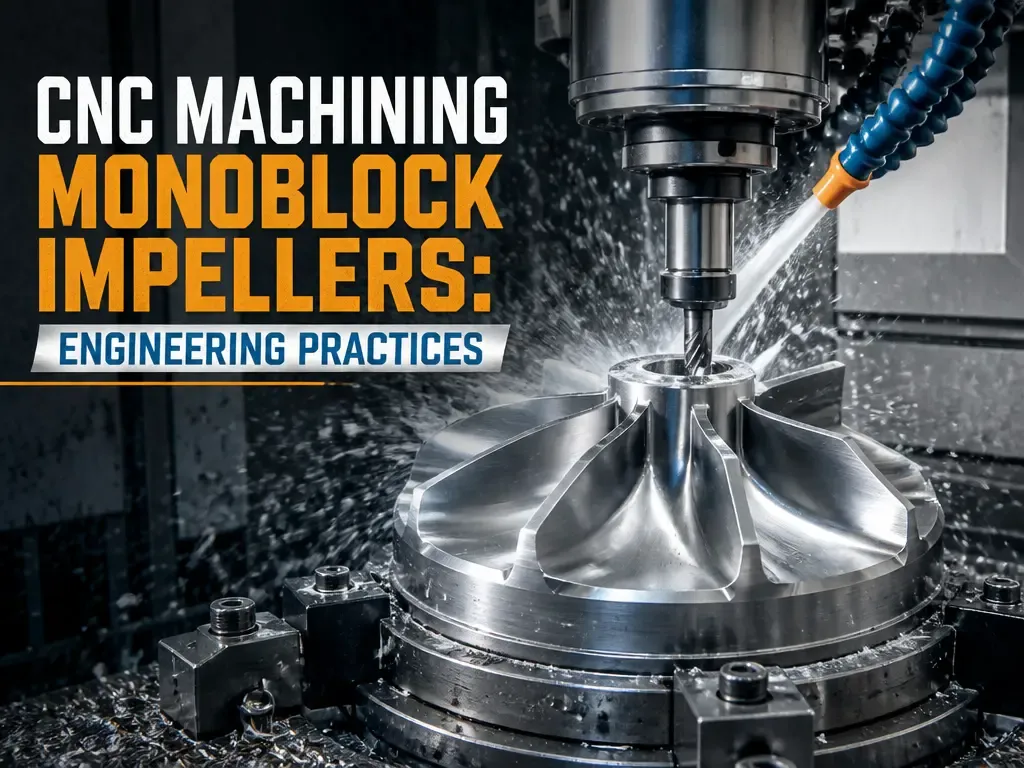
Impellers are among the most demanding components in fluid power systems, serving as the core elements for energy conversion and fluid transmission across aerospace, energy, and automotive applications. For monoblock (integral) impellers, CNC machining has become the dominant manufacturing method because it can produce the complex, continuously curved surfaces that define impeller performance.
The quality of an impeller directly affects equipment efficiency, energy consumption, and long-term operational stability. This article examines the engineering challenges of machining monoblock impellers and the process strategies that produce reliable results.
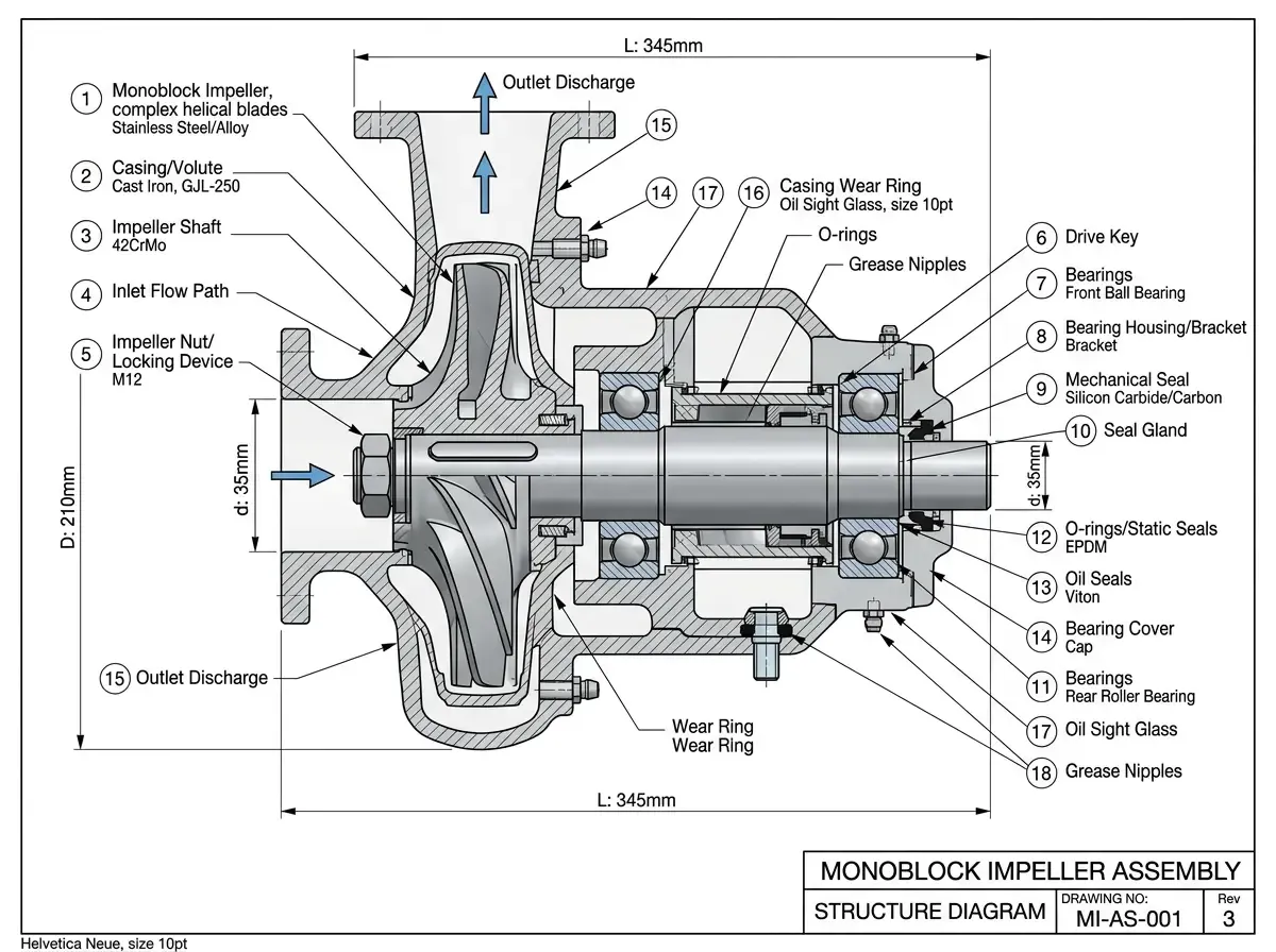
Monoblock Impeller Structure
A typical monoblock impeller consists of three integrated sections:
- Disc — The circular base that supports the blades and defines the flow passage floor
- Blades — Curved surfaces distributed evenly around the disc, responsible for fluid energy exchange; their shape directly determines aerodynamic or hydraulic efficiency
- Hub — The central section that connects to the drive shaft and transmits rotational power
Because these elements are machined from a single piece of material rather than assembled, the structural integrity is higher, but the machining complexity also increases significantly.
Why Impeller Machining Is Challenging
The primary difficulty in machining monoblock impellers comes from the combination of complex freeform blade surfaces and the narrow gaps between adjacent blades.
Tool access and collision risk
As the cutting tool moves through the blade channels, it must maintain a precise orientation that avoids contact with both the blade surfaces and the hub floor. Because the spacing between blades is often very tight, the available tool diameter is constrained, and the tool must be angled continuously to reach all surfaces without interference.
Tool axis vector control
Maintaining the correct tool axis vector throughout the cut is one of the hardest problems in impeller machining. Traditional CAM systems can struggle to control these vectors accurately across the full range of blade curvature, which can lead to overcutting, undercutting, or surface finish defects in critical areas.
Programming complexity
Even with modern software, impeller toolpath programming has historically required significant operator experience. Manual adjustment of cutting paths and tool orientations is time-consuming and makes consistent quality difficult to achieve across multiple parts or production batches.
How Five-Axis Machining Addresses These Challenges
Modern 5-axis machining technology and advanced CAM software have substantially improved the impeller manufacturing process.
Today’s CAM systems often include dedicated impeller modules. Once the engineer defines the basic geometric features — hub profile, blade surfaces, and root fillets — the software can automatically generate optimized tool paths and machining parameters. This approach reduces dependence on individual operator experience, shortens programming time, and produces more consistent results across production runs.
Key advantages of this approach include:
- Automatic collision avoidance across the full toolpath
- Optimized tool axis vectors for smooth surface finish
- Consistent stepovers that maintain uniform scallop height
- Multi-stage strategies that balance material removal rate with surface quality
A Practical Process for Aluminum Impeller Machining
To illustrate how these principles come together, consider a typical high-speed centrifugal compressor impeller machined from aerospace-grade aluminum alloy. Parts like this require tight tolerances, good surface finish, and a process that can deliver repeatable results in small to medium batch sizes.
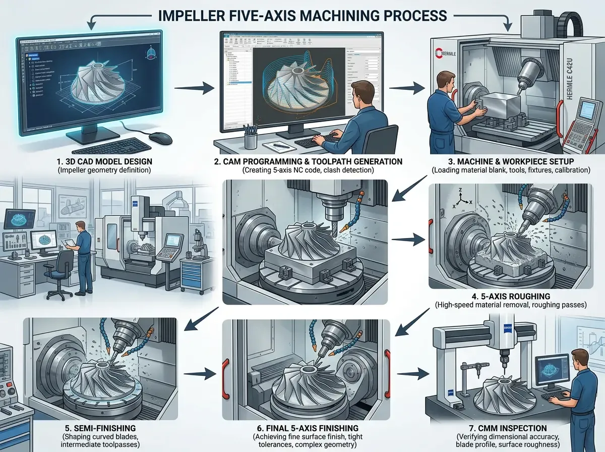
The typical process flow moves through four stages: turning for the base geometry, five-axis milling for the blades, simulation and verification, and final quality inspection.
Turning the base geometry
Before machining the blades, the outer profile, top and bottom faces, and center bore are turned to size on a CNC lathe. Since these features are surfaces of revolution, turning is both the most efficient method and the one that produces the best surface finish for the hub and disc body.
Five-axis toolpath strategy
The blade geometry is where the process becomes more demanding. For aluminum impellers, the blade surfaces require continuously varying tool axis vectors to maintain proper cutting engagement across the full profile.
A staged approach typically works best:
- Roughing — Remove the bulk of material between blades, leaving an even stock allowance
- Semi-finishing — Bring the surfaces closer to final form while managing tool deflection
- Finishing — Achieve the final surface quality and dimensional accuracy
Each stage uses different tooling and parameters. The roughing stage prioritizes material removal rate, while the finishing stage focuses on surface quality and tolerance control.
Before any metal is cut, the complete toolpath is verified in a machining simulation environment. This catches potential collisions, checks material removal, and validates tool axis behavior before the program reaches the machine.
Quality verification
Once the part is machined, verification goes beyond simple dimensional checks. For impellers, the key inspection points include:
- Blade profile accuracy against the CAD model
- Surface roughness across critical flow surfaces
- Blade-to-blade spacing and symmetry
- Hub and bore concentricity
High-precision CMM (Coordinate Measuring Machine) inspection is typically used to generate a full dimensional report, confirming that every critical surface falls within the specified tolerance band.
What to Prepare Before Requesting a Quote
If you are developing an impeller and plan to work with a CNC machining partner, a well-prepared RFQ leads to better process decisions. Useful preparation includes:
- A complete 3D CAD model with the blade geometry fully defined
- Material specification including any heat treatment requirements
- Surface finish targets for critical flow surfaces
- Tolerance requirements, particularly for bore concentricity and blade profile
- Expected quantity and whether the job is prototype or production
- Any known machining challenges from previous builds
Without this context, a supplier may over-process features that are not functionally critical or underestimate the difficulty of surfaces that matter most to performance.
At Zigitech, our precision machining team reviews each impeller project by evaluating geometry complexity, material behavior, tolerance relationships, and the real functional priorities of the part. The result is a process plan that balances quality, lead time, and cost.
Conclusion
Manufacturing high-quality monoblock impellers requires the systematic integration of engineering expertise, advanced CAM software, five-axis machining capability, simulation tools, and precision metrology. Each element contributes to a process that can reliably produce the complex curved surfaces that impeller performance depends on.
The most effective approach is not simply to use the most advanced machine available, but to match the machining strategy to the specific geometry, material, and functional requirements of each impeller.
If you are working on an impeller project and need engineering support for machining, request a quote with your CAD files and specifications. An engineering-led process review is the most reliable first step toward a successful build.
