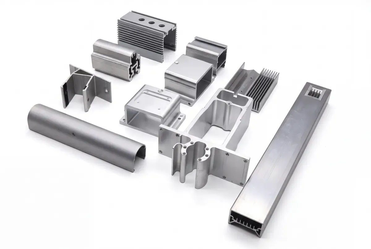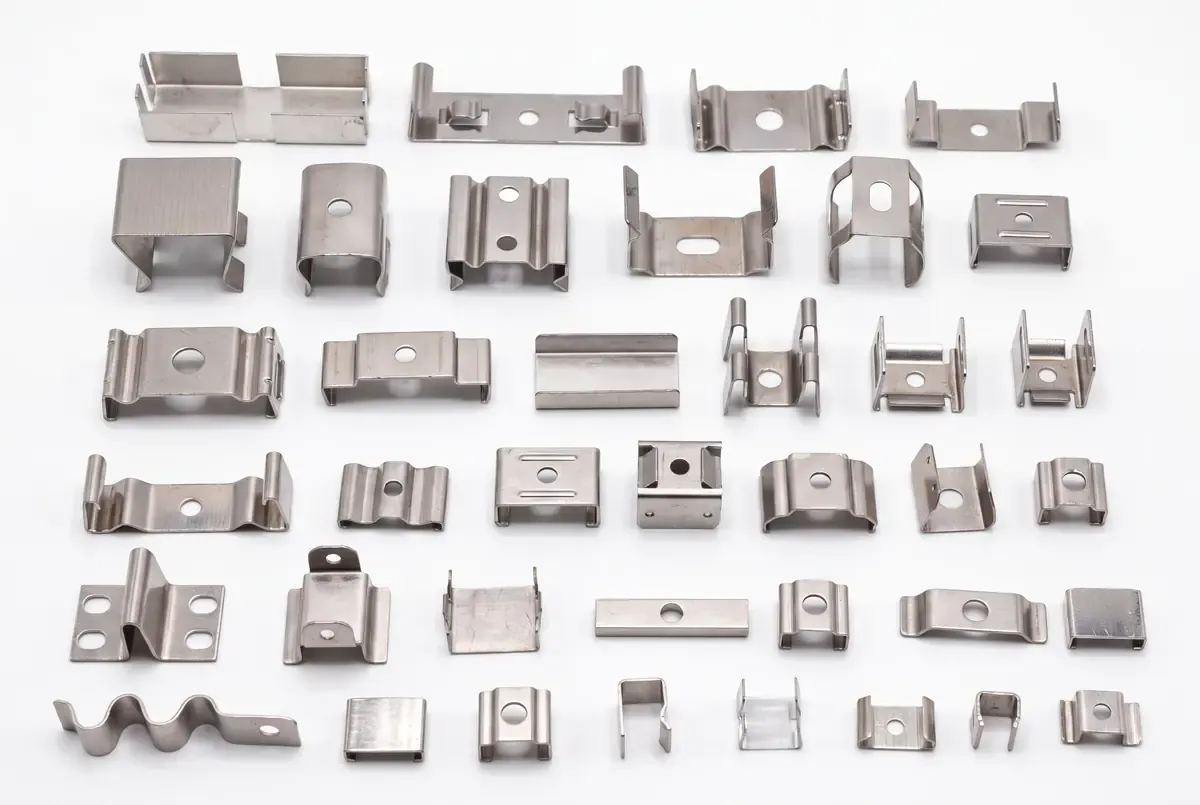
Stamping uses a press and tool to cut or plastically form metal stock into a part. Depending on the design, the operations may include blanking, piercing, bending, drawing, or local forming. The press stroke is visible, but most repeat-production risk lives in the material, feed, die, setup, and acceptance method around it.
This checklist is for engineers and buyers reviewing a new stamped component or an existing supplier process. It translates practical production controls into questions for a sheet metal fabrication RFQ. It is a review framework to adapt to the control plan agreed for a specific drawing.
Know which operation makes the feature
Blanking and piercing separate material to create an outside contour or internal opening. Bending changes the angle of a sheet region. Drawing turns a flat blank into a cup-like or deeper three-dimensional form. Local forming creates details such as flanges or embossments without removing the whole feature.
One part may need several of these operations, either in separate steps or a progressive tool. The process choice depends on geometry, thickness, material behavior, forecast volume, and the quality needed at the finished interface. For designs still changing, laser cutting and CNC bending may offer a more flexible validation route.
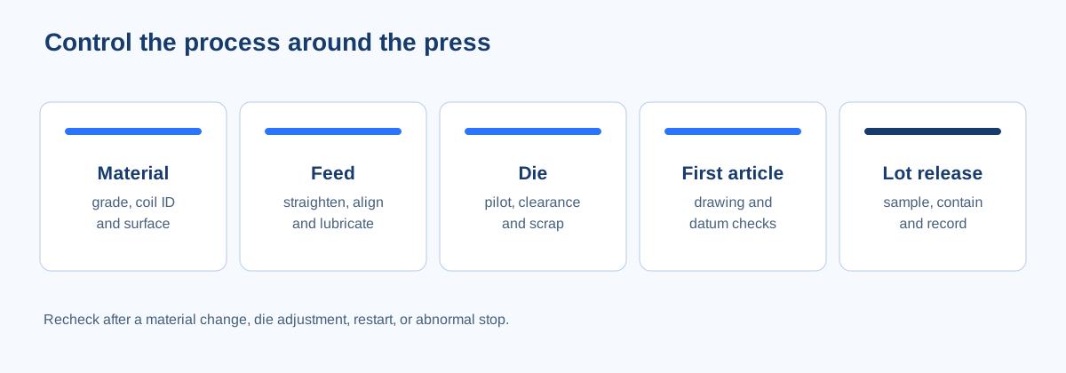
Before the first stroke: material and feed
Check that each coil or blank can be connected to its material specification and lot. Confirm thickness, width, surface condition, and any properties linked to critical part features. Packaging and handling should protect material from corrosion, scratches, and contamination before it enters the press.
The feed system should present material to the tool at the correct position and progression. Straightening, guides, rollers, and contact surfaces need to be clean and set for the stock being run. A press-line supplier’s coil feeding description illustrates how decoiling, straightening, and intermittent feed work together.
During setup: die, lubrication, and scrap
Confirm the die revision and setup record before production starts. Review pilot engagement, feed release, clearance, and whether a misfeed can be detected. Lubrication must reach the intended forming area without contaminating the finished part; filters and low-flow responses should match the process risk.
Scrap and slugs need a defined exit route. A trapped slug can mark a surface or damage a die, while an unobserved strip shift can make many nonconforming parts quickly. Where the tool and press support it, sensors and stop conditions can help contain these failures. The Precision Metalforming Association’s training topics include die protection, inspection, tool maintenance, and process diagnostics for this reason.
Approve a first article that represents the run
An approved first article should be compared with the current drawing and any reference sample using a documented sequence. Measure the features that control fit, then check burr direction, surface appearance, form, and any installed hardware. Record the material and setup tied to the approval.
Define what happens after a restart, die adjustment, coil change, or abnormal stop. Parts produced during an unstable transition need a clear hold, inspection, or rejection rule. A last-article check can help determine whether a tool drifted during the run and whether the next setup needs attention.
Monitor the batch, not only the first part
In-process sampling should target the features most likely to change: hole position, form height, flatness, burr condition, or surface damage. The frequency depends on risk and the agreed quality plan. Die wear, scrap accumulation, and changes in feed or lubrication should have a defined response, not a note left for the next shift.
Finished parts also need safe collection and packaging. A correct stamping can still fail final assembly if edges are bent in a bin or cosmetic faces rub together during transport. Our formed enclosure case shows why these downstream conditions belong in the manufacturing brief.
Questions to include in a stamping RFQ
- Which features and datums are critical to assembly?
- Is the drawing stable enough to justify dedicated tooling?
- What are the expected batch and annual quantities?
- Who owns the tool, and what is its revision and maintenance history?
- Which first-article, in-process, and final records are needed?
- What finish, hardware, and packaging are part of the accepted part?
When you request a quote, send the drawing, material, volumes, and any existing tool data. A useful quote should explain the proposed route and its control points, not only the press capacity or unit price.