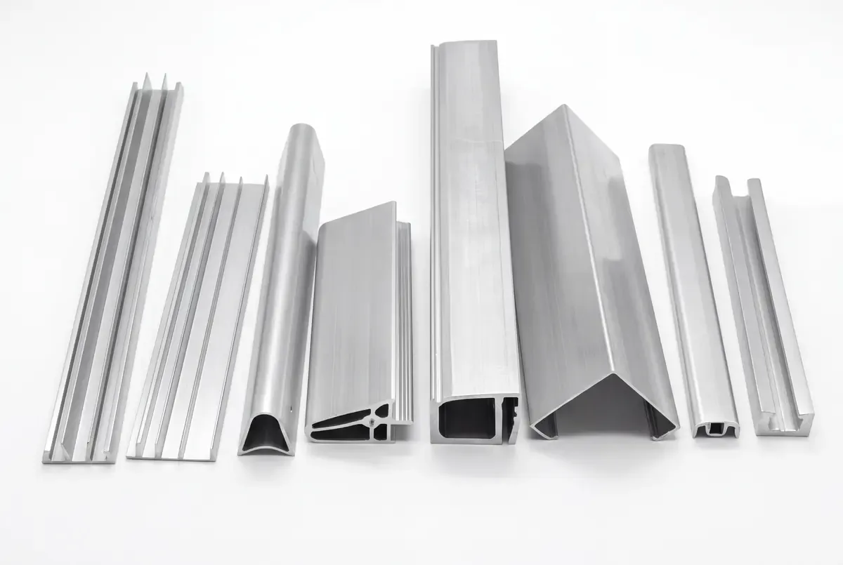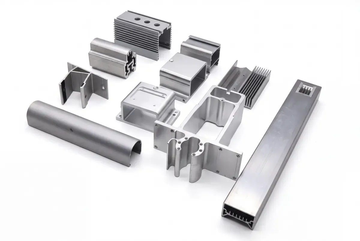
An aluminum extrusion die is more than an opening with the desired outline. It has to guide metal into thin and thick areas at compatible speeds while resisting the load of the press. This is why a small change to a profile can change tooling risk, trial work, and the quality of the resulting length.
At ZigiTech, a profile review connects the functional section to the die plan and the finished-part drawing. This guide translates the important engineering decisions into questions a product team can answer before ordering a custom profile. Explore our custom aluminum extrusion service for the complete route.
Start with the profile class
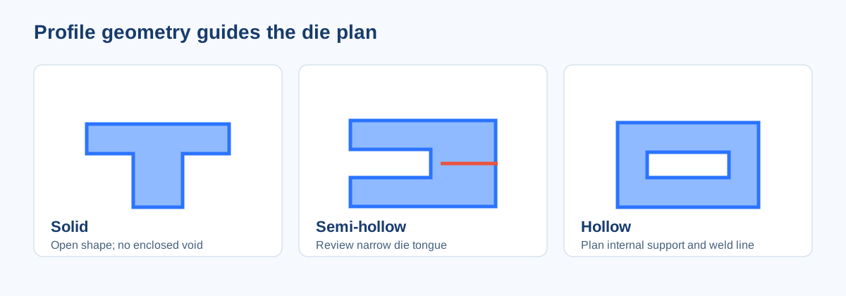
Extruded sections are commonly described as solid, semi-hollow, or hollow. A solid shape has no enclosed void. A semi-hollow shape has a partly enclosed region that can leave a narrow die tongue. A hollow section surrounds at least one complete void and usually needs a die arrangement that supports an internal mandrel.
The classification is useful because it changes how the die is supported and how metal reaches the final opening. The Aluminum Extruders Council describes these three classes and highlights the value of balanced walls, rounded transitions, and avoiding fragile deep tongues.
Why metal-flow balance matters
Metal does not automatically travel through every portion of a complex opening at the same speed. Thin walls, asymmetric mass, and isolated features can produce uneven flow. The profile may bow, twist, or show variation along the length even when the nominal die opening looks correct.
Die designers can adjust entry geometry, feeder features, and bearing lengths to influence local flow. These decisions are specific to the alloy, section, press, and operating conditions. A first trial then tests the real profile, and any correction should be based on measured shape and surface results.
For the product drawing, the most useful inputs are:
- the faces that locate or mate in the assembly
- wall areas that are structurally important
- surfaces that will remain visible after finishing
- cut length and any straightness or twist requirement
- local features that will be created later by CNC
Turn die geometry into a process plan
The article that prompted this guide examined a feature-based process-planning approach. In practical terms, a die can be described through recognizable features such as openings, pockets, support surfaces, and bearing regions. The underlying research paper proposes searching a library of previous die-manufacturing cases with a neural-network method, then reusing or revising a similar plan.
The useful sequence is to identify the new die’s features, find comparable past features, propose a machining route, and have an experienced planner check the fit. A case library can make prior decisions easier to retrieve, but the similarity of two sections does not prove that they will behave alike on a particular press. The actual die still needs detailed machining, assembly, heat treatment where specified, inspection, and an extrusion trial.

For a buyer, the actionable lesson is to document profile features and acceptance criteria clearly. That makes the die review repeatable even when planning is carried out by people rather than a search system.
Design changes that often simplify the die
Keep walls reasonably balanced
A sudden thick-to-thin change can make flow and cooling harder to control. If the function permits it, redistribute material or use a smoother transition. The goal is not a universal wall thickness; it is a section that can flow predictably while meeting strength and thermal requirements.
Reduce fragile tongues
A narrow, deep opening may leave a weak projecting feature in the die. Widening the opening, changing its depth, or splitting the function into another feature can improve tooling robustness. Hollow and semi-hollow details should be reviewed early because they can change die type.
Separate profile tolerance from machined tolerance
A profile-wide tolerance is not always the right way to control one critical mounting face. A local CNC milling operation can establish a datum or precise hole pattern after extrusion. Put those features on the finished drawing and inspect them after machining.
What to validate at the die trial
Measure section dimensions, straightness, twist, surface quality, and any potential weld-line location for hollow shapes. Record the alloy, temper route, die revision, and press conditions tied to the accepted trial. The trial is the point at which assumptions about flow become observable facts.
The Aluminum Association’s tolerance resources explain why straightness, twist, flatness, metal dimensions, and space dimensions need different measurement approaches. Avoid putting one blanket number on every feature.
From accepted profile to usable part
Die approval is only part of the program. Cut length, machining, finishing, and packaging still determine whether the part will install cleanly. Our heat sink profile case shows how a finned section and its machined mounting interface are planned together. For the full cost picture, read extrusion process and cost drivers.
Send the section, finished-part drawing, expected volumes, and critical surface notes when you request a quote. Those inputs let the die review focus on the features that actually govern the part.